First Time Right is becoming mandatory for the manufacturing industry to save costs and increase profitability. Add to it the requirement that ideas need to be translated to product and brought to market faster, the situation looks untenable. There is increasing pressure on design to address all these challenges.
Every department in a manufacturing organization has to deal with drawings either directly or indirectly. They get influenced by the drawing, its correctness, completeness and alignment with the quality objectives of the company. If there are errors on the drawings, assumptions made due to the incompleteness of the drawing representation, then the organization bleeds in terms of re-work, rejections, recalls and delays that cost money.
Why is GD&T Important?
ASME Y14.5 – 2009 Version of Geometric Dimensioning & Tolerancing (GD&T) Standard on Engineering Drawing and Related Documentation Practices states in its Foreword, thus, ‘This revision contains paragraphs that give a stronger admonition than in the past that the fully defined drawing should be dimensioned using GD&T with limit dimensioning reserved primarily for the size dimensions for features of size.’
This statement comes as a result of deliberations on the poor quality, assumptions in part definition that go with incomplete and intrinsically deficient approach using Plus/Minus Tolerancing. It is incumbent upon Engineering Industries to adopt the GD&T practices that have been proven to deliver in terms of costs, quality, reliability and safety.
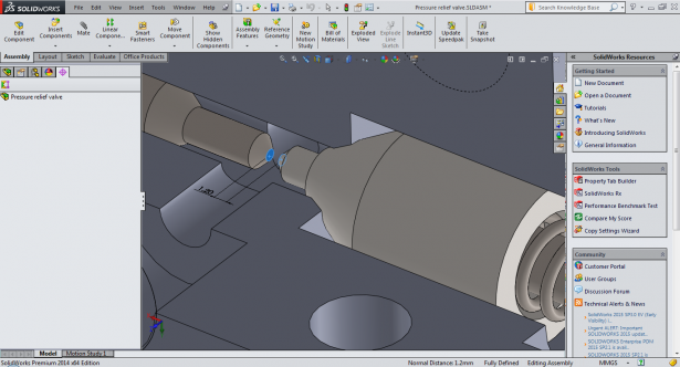
Let us look at the example of a Pressure Relief Valve shown in Figure below:
If we look at the Plunger that is housing the spring and located inside the housing (Body), the sequence of assembly is evident.
This process of identifying the assembly process and sequence enables the selection and prioritization of the Datums. This step of identifying the Datums is critical to avoid downstream Quality issues.
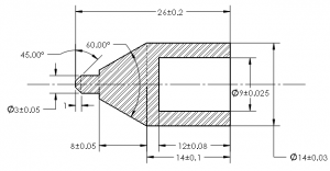
Conventional Plus/Minus Tolerance based drawing would be similar to the following:

This drawing creates more confusion regarding the setup for Manufacturing and Inspection since it does not clarify how the designer intended to control.
Simple Steps towards a Correct & Complete G D & T Drawing
Step 1: Define Part features that would serve as origin with specific directions for measurement
This step relates to Datums. Datums need to be selected based on the following criteria:
1. Representative of Mating Features
2. Reflect Functional Assembly
3. Stable
4. Repeatable
5. Accessible
All of the above criteria are equally important. The choice and order of Datums Selection need to be in alignment with the Quality objectives we intend to protect. In other words, Design For Assembly (DFA), that influences Datum Selection and Precedence (order), needs to be in alignment with Design For Quality (DFQ) objectives.
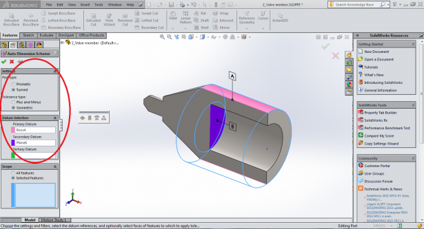
In this case, the datums would be as shown in the picture below.

Step 2: Specify Nominal (Basic) Dimensions for Location and/or Orientation of Features from Datums
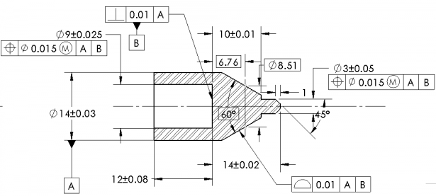
In our example, since the Cylindrical and Conical features are located concentric to Datum A, they are at Zero Basic Dimension and hence not shown.
Step 3: Specify Tolerance Zone Boundaries for Part Features in terms of shape and size along with specific rules for compliance

This step requires knowledge of process capability existing (with the organization or suppliers). Additionally the dimensioning schema should have the least number of dimensions between the datum reference and features that form a part of the measurable Design for Quality Objective. This is essential to identify the correct Critical To Quality (CTQ) or Key Characteristics for the part that would help in inspection and reporting. In comparison to the Plus/ Minus Tolerancing Schema, the GD&T approach ensures clarity in setup during manufacture & inspection, alignment with Quality objectives while keeping cost as a driver for change.
Step 4: Allow Dynamic Interaction of Tolerance Zones between Features in a Part, and across parts, simulating Assembly possibilities for Maximizing Tolerances
This step differentiates G D & T from Plus / Minus Tolerances in enforcing a methodology that would help reduce cost while meeting Quality objectives. Drawing is incomplete without this step. Even companies that incorporate GD&T, fall short of this requirement, sometimes leading to an erroneous conclusion,that GD&T is expensive and its impact on quality is not significant.

Step 5: Cost of Precision Vs Cost of Poor Quality Analysis for Optimal Tolerances
By choosing alternate Process Capability, providing costs incurred to maintain specified tolerances and performing a risk assessment based on Risk Priority Number (RPN) of Design Failure Modes & Effects Analysis (DFMEA), a designer can arrive at optimal tolerances and provide KC’s (Key Characteristics) on drawings. This step ensures that management is provided with alternatives in terms of costs, choice of suppliers and investment in machinery and manufacturing lines to achieve desired levels of quality in an objective manner.
Benefits of incorporating G D & T
While there are many benefits implementing GD&T, some of them stand out as compelling reasons to change, as under.
- Elimination of errors, re-work, rejections and scrap
- Fail safe approach to tolerancing
- Easy to identify deviating processes that affect Quality and restore them for maximizing yield
- Improved Product Reliability

EGS India
Categories: Design, Let’s Go Design, SOLIDWORKS


