


February is a big month for SOLIDWORKS users, with 3DEXPERIENCE World taking place in Dallas, Texas next week. Plus, today we launch the latest updates for our cloud-connected and browser-based design roles. The latest functional delivery (FD) release, R2024x FD01 is packed with user experience and performance enhancements for 3D Creator, 3D Sculptor and Manufacturing Definition Creator.
Enhancements include a new command search to easily find commands, the ability to document holes with a single tool, snap points for inserting pictures more precisely and more!
Let’s take a look at the top enhancements.
USER EXPERIENCE
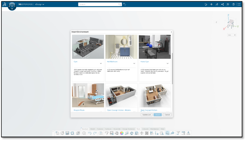
Design in the Context of an Experience – Visualize your product within a real-world design environment.
One of the biggest user experience features is the ability to design in the context of your environment by inserting design environments. This is a great feature that helps you vividly visualize your products in their intended surroundings and ensure that products are designed to the correct scale. Elevate your design process with this feature and achieve excellence in product design.
Choose from a gallery of environments, including a gym, hospital room, kitchen, and living room.
This new feature will also help you create the experience for partners and clients so you can easily share your vision and win them over.
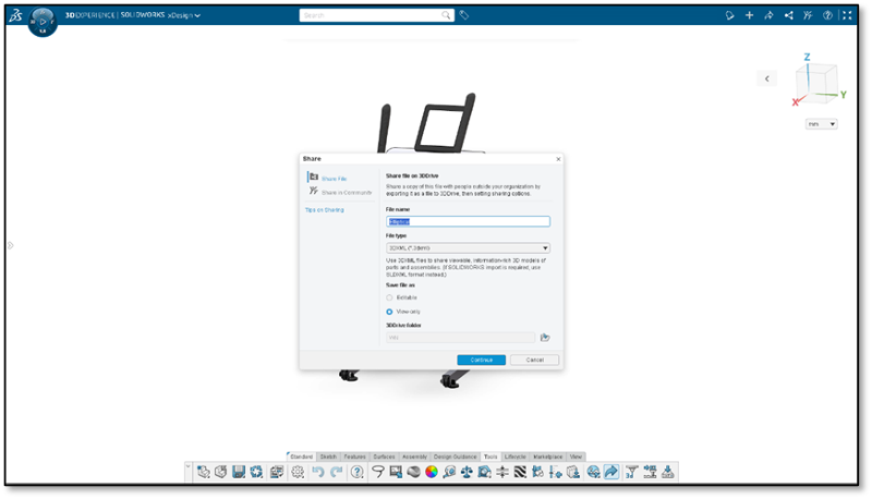
Streamlined Sharing Options – share in communities and externally through 3DDrive from one convenient space.
Simplify your workflow with access to all sharing options in one place, such as Share File, Share in Community and more! Now you can access all from one command in the action bar and share directly from 3DDrive. You can also share externally from this new share menu as well.
Command Search – find the tools you need fast!
This is a favorite in SOLIDWORKS Desktop and now it’s here in the browser-based design roles! Find and open commands fast with new options, including searching for commands through the S Shortcut menu, directly from the Action bar, or simply pressing the / key on the keyboard. You can search for commands by the command name, keywords in the tooltip description, or common synonyms from other CAD systems.
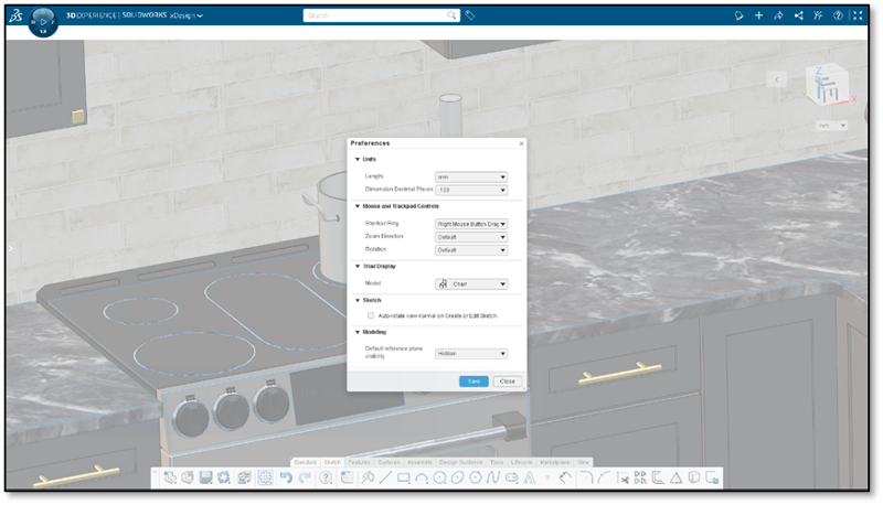
New Options in Common Preferences – Take command of your design environment with the redesigned Preferences dialog.
The Common Preferences menu has been expanded with new options that allow you to control automatic view navigation during sketching, default plane visibility, and rebuild method.
PART & ASSEMBLY DESIGN
Incorporate Lattices into Designs – easily integrate lattice structures with the rest of your design.
Now it’s even easier to incorporate lattice structures into your designs. Integrate lattice geometry into your designs by referencing lattice geometry in sketches to build more cohesive connections between lattice and parametric geometry. For instance, you can dimension to lattices or convert lattices into sketch entities.
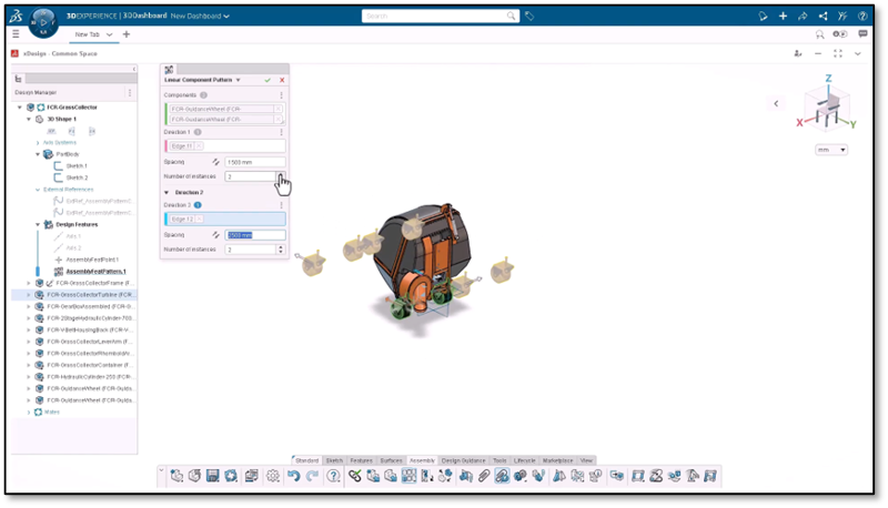
Insert and Replace Components – speed up design iterations by locating components quicker.
It’s easier than ever to find components when using the Insert and Replace command as you can access recent content or launch specific search queries to find the desired component. Enhance your workflow by quickly accessing recently used or relevant content.
This works just like the Open From command, and now it’s right at your fingertips when dealing with components.
External Reference Management – track and resolve outdated and broken references faster.
We all know dealing with broken references can be time consuming. To ease that burden, you can now identify outdated or broken external references faster. You’ll notice new badge icons in the Design Manager to alert you of references issues for features and geometry. When you hover over the icons you will see a descriptive error message, such as “Broken Reference” or “Out of Context” so you can identify and fix the problem and carry on with your design.
Repair Lost References – easily identify and restore entities.
Repairing lost references can also be a pain! Using the new Edit on Edge command you can rectify lost references on converted entities through one intuitive dialog, ensuring a smooth and error-free design process. Easily identify which entities have been lost by the warning icon in the selection chip for the lost entity in the dialog.
For example, if you have a broken reference, like a sketch constraint, due to upstream edits while you’re working on a new design iteration, you can easily fix those with this new Edit on Edge command.
Solve Out-of-Date Assemblies – get rid of clutter in the Design Manager with just one click.
When you open an assembly and it’s outdated and hasn’t been solved, you’ll receive an error message prompting you to solve the product. Typically, when an assembly is out of date, the Design Manager will be flooded with error messages. To fix that you can just hit “Solve product” in the warning message that pops up and the error messages in the Design Manager will disappear.
Last, when it comes to performance, exiting a sketch, using Pattern and Mirror for preview generation and using commands for body selection are much faster.
MANUFACTURING DEFINITION
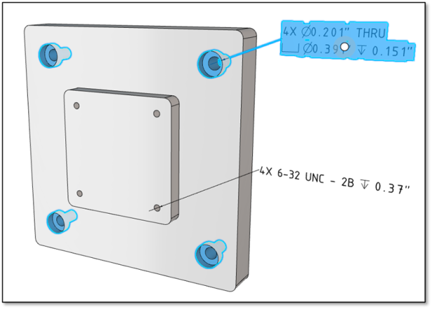
Hole Callout – ensure proper fit and function with a single tool!
There’s a new Hole Callout tool that enables you to define any hole, or hole pattern that was created as a hole feature in xDesign.
Hole callout provides the complete comprehensive hole information required for manufacturing such as depth, thread, counterbore, countersink, instance count and so on.
The single easy to use command ensures your hole information is always in sync with the model and will help you efficiently define the hole fit and tolerance, proper hole fit, sizing, positioning and tolerance.
Lattice Support – create production-ready definition for complex lattice and 3D printed components.
You can now bring in components that contain geometry from CATIA Lattice Designer and annotate models that contain lattice geometry.
Annotation Level Font Control – enjoy full flexibility and customization for fonts.
You now have new font control options for each individual annotation type, including datums, balloons, etc. within the system and document option menus
This gives you full control over each specific annotation type, giving you the added flexibility to create the drawing the way you want and point out things that you don’t want the manufacturer to overlook, eliminating issues.
Drawing View Activation – save time by accessing annotation commands directly within the drawing environment.
Now when you’re in the drawing environment you will see all the commands on the Action bar. If you recall they were previously grayed out and you had to select a view.
So now all you have to do is activate the annotation command, select any existing geometry or view frame to automatically activate the corresponding view and begin placing annotations.
FREEFORM DESIGN
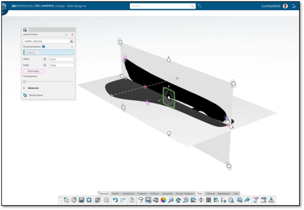
Snap Points for Inserting Pictures – get more precise placement when adding multiple pictures.
Use snap points to better align, orient, and size multiple pictures.
By adding snap points, you can align and scale images from different planes, giving you greater accuracy in your designs.
Alternate Robot for Modifier Commands – modify the mesh directly from the robot.
Access additional mesh modification options directly from the robot via Modifier Robot that includes options like extrude, crease edge, and insert loop, instead of having to launch the command from the action bar or right click.
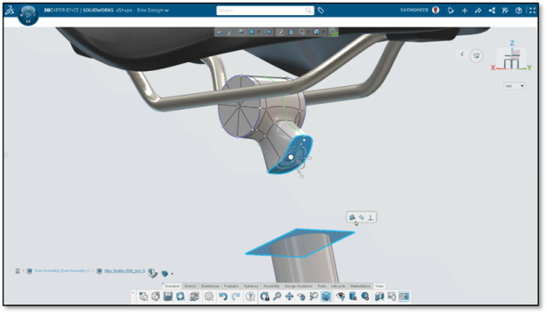
Align to External Geometry – easily design a freeform shape around existing geometry.
Align your subdivision mesh to an external geometry by making it coincident, colinear, perpendicular or parallel to that geometry.
Easily align subdivision faces or geometry to an external geometry. For example, you can select different faces of a subdivision then select an external geometry like a plane to make it parallel or perpendicular. This provides more control to manipulate your mesh so that it better aligns to existing geometry.
That’s a glimpse of what’s new this round. If you happen to be attending 3DEXPERIENCE World you can catch me and my colleagues in these presentations to learn more about cloud-connected and browser-based roles available in the 3DEXPERIENCE Works portfolio and the SOLIDWORKS Cloud Offer.
Safe travels everyone and looking forward to seeing you in Dallas!
If you missed the last update, check it out here.

Categories: 3D Creator, 3D Sculptor, 3DEXPERIENCE, 3DEXPERIENCEWORKS, Cloud Computing, Collaboration, Dassault Systèmes, Design, Manufacturing, Product Designers and Mechanical Engineers, SOLIDWORKS, What’s New 3DEXPERIENCE Works Design