


In my last blog, I underlined the importance of driving MBD from top down. The following natural questions are what the specific benefits of MBD are, how to obtain support from top, and how to handle objections. These two blogs “Don’t hesitate” (Part 1 and part 2) will try to answer these questions from people mindset perspective.
As mentioned in the MBD Implementation 10 DOs and 10 DONTs Introduction blog, MBD is a natural thought and 58% of SOLIDWORKS users have considered defining Product and Manufacturing Information (PMI, such as Dimensions, Tolerances, Datum, Bill of Materials, Surface finishes, Notes, Weld symbols, and associated metadata) to 3D models directly. Meanwhile, there are also concerns on shifting away from the current 200-year-old 2D drawing tool. Before addressing these concerns, let’s remember: hesitation is not free and could be pretty costly due to the associated opportunity cost.
For example: some machine shops are asked by clients what 3D PMI formats they can read instead of 2D drawings for future contracts. Some are starting to receive 3D PDF documents more regularly. Some suppliers even lost contracts because of non-compliance with Military-Standard-31000A, a U.S. military standard published in 2013 to define MBD schema and requirements.
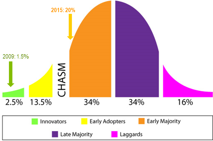
On the other hand, there are also businesses who have established MBD as a competitive strategy to move up in the supply chain. Furthermore, 20% of SOLIDWORKS users have started defining 3D PMI in 2015, a big jump from 1.5% in 2009 in Figure 1. This indicates MBD has crossed the chasm between Early Adopters and Early Majority on the Geoffrey Moore technology adoption curve in Figure 1 and MBD is becoming a majority technology. In fact, Japan Electronics and Information Technology Association (JEITA, the governing body of Japan Industry Standard (JIS), equivalent of ASME in U.S.) specifically toured Europe and U.S. in 2014 to learn the latest developments from manufactures and DS SOLIDWORKS Corporation. Now the MBD JIS is being defined. Facing this fast-growing trend and opportunity, can we really afford to hesitate?
Now what are some common MBD objections?
Can MBD really save time?
Many companies questioned: “Even if 2D drawings are skipped, we still need to define 3D PMI. Where would the time-saving come from?” Let’s think from the entire product lifecycle standpoint beyond PMI definition for a moment. One key benefit of MBD is that unambiguous and semantic 3D PMI can greatly improve downstream manufacturing productivity.
Table 1 shows some early results at Boeing and Toyota. More recently in 2014, Rolls-Royce conducted an MBD program and summarized the following specifics. First, semantic PMI enabled machine interpretable product definitions for inspection and machining. It also facilitated knowledge and design intent sharing. Second, semantic PMI enables data re-use by downstream supplier systems and processes, such as manufacturing and inspection, which reduced time for data re-entry into machining software, information redundancy, human interpretation errors, and re-work (models & parts) and scrap (parts). (Source: Technical Data Package (TDP) for the Digital Enterprise, Rolls-Royce Corporation, 2014).

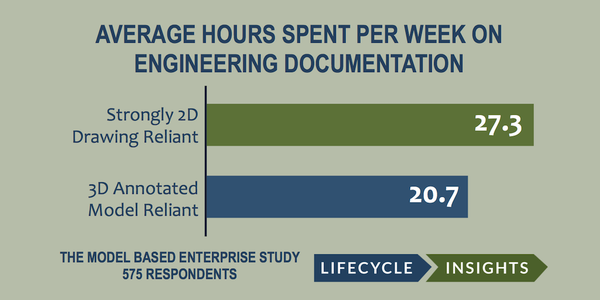
Besides these individual examples, an independent research by Lifecycle Insights in May 2015 looked into mass market manufactures and performance differences. Regarding average hours spent per week on creating, clarifying, and amending engineering documentation, this research found out that companies who are strongly 2D Drawing reliant spend 6.6 hours more than those who are 3D annotated model reliant.
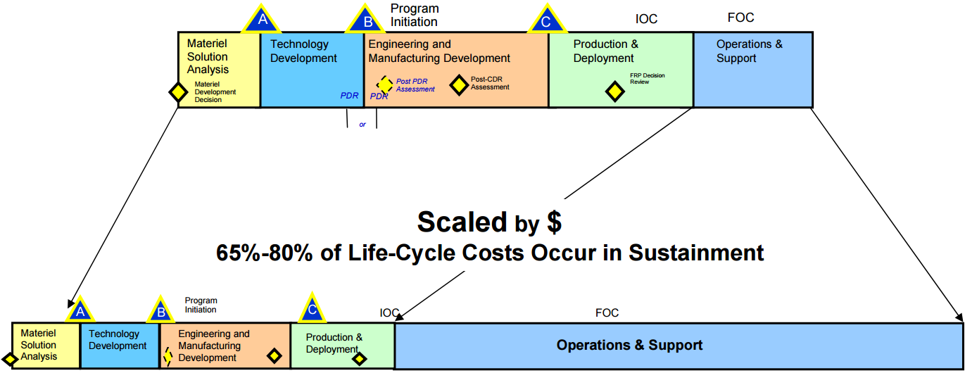
One step further, U.S. Army research found out the lifecycle of modern products is much longer. For example, B52 bomber expects 94 years of life. In this long lifecycle, 65% to 80% of costs actually occur in sustainment such as operations and support after deployment (Source: Reuse of Model Based Definition Data to Increase Army Efficiency and Reduce Lifecycle Costs, Technical Data Package Specification for 3D MBD and MIL-STD-31000 Overview, Paul Huang, 2010).
In such a long cycle, 2D drawings are very easy to get out of sync with 3D design, even worse for printed copies due to expensive paper file management, wearing out, poor legibility, and so on. However, MBD integrates PMI into 3D digital models, which is much easier to manage, maintain, upgrade, and search.
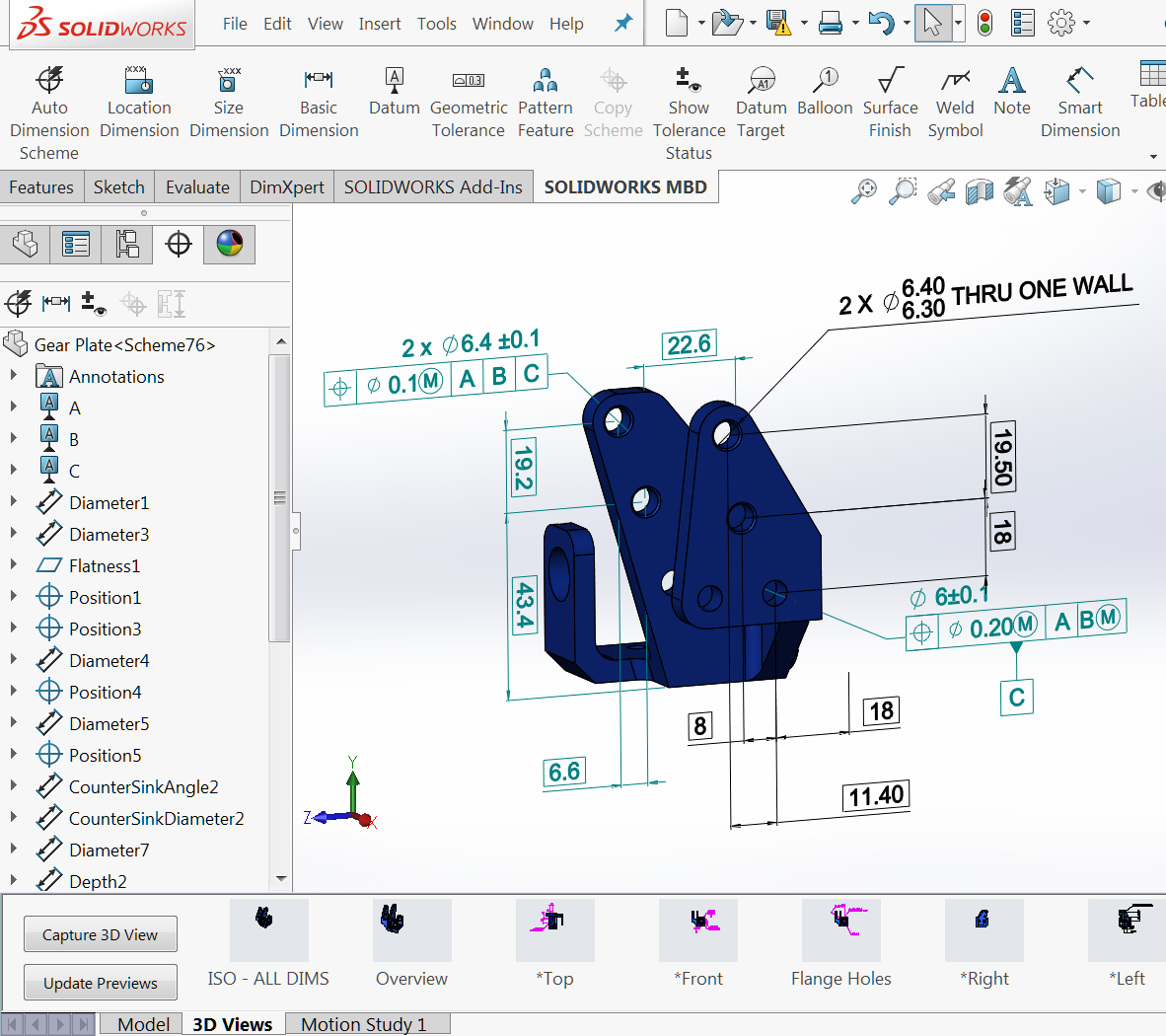
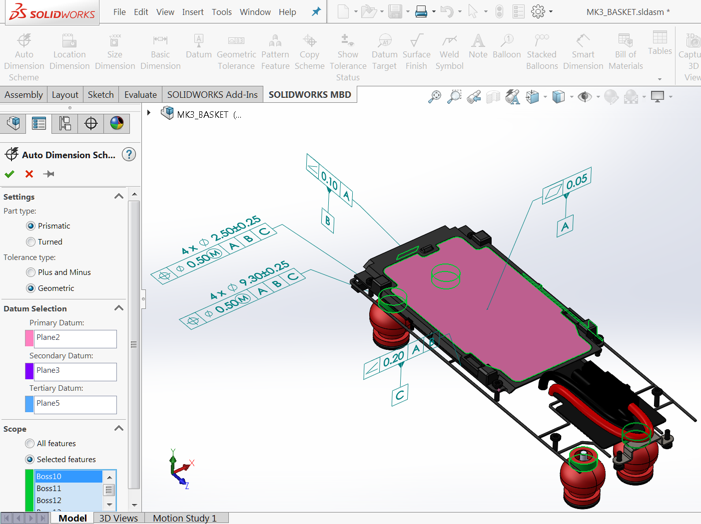
Even just for PMI definition alone, MBD can still save time because model itself contains feature and sketch dimensions and tolerances, which can be exposed and reused quickly instead of recreated (Black bold items in Figure 4). SOLIDWORKS DimXpert also provides automatic dimensioning capability. Users can just pick model type, tolerance type, datums, and features to define (or an entire model), DimXpert adds PMI automatically, even for imported bodies (Figure 5).
My next blog “Don’t hesitate” Part 2 will continue this topic by looking into other common objections such as 2D drawing status quo, upfront investment, and supply chain adoption. To learn more about SOLIDWORKS MBD, please visit its product page. Also welcome to discuss with me at Twitter (@OboeWu) or LinkedIn (OboeWu).
Oboe Wu
Categories: Engineering 4.0, SOLIDWORKS, SOLIDWORKS MBD